Intended Operation
The color organ was intended to use an audio signal to light up different color LEDs, in our case red (bass), green (mids), and blue (highs). Ideally, these LEDs would only play the sounds at these frequency, and not at others. That is, as soon as a frequency surpasses the bass frequency, the red LED would turn off and the green LED would turn on.
Criteria for Success
There were two major criteria for success in our project:
1.) The color organ must emit different colors of light at different sound frequencies.
2.) Low frequencies would correspond to red LEDs, mid-level frequencies would correspond to green LEDs, and high frequencies would correspond to blue frequencies.
Pert Chart
 |
We began researching schematics and techniques for building a color organ. We came across a circuit that used transistor based filters in order to control when certain LED's would light up. We should the schematic to the professor and gained approval.
 |
Once we gained approval, we proceeded to create the actual circuit. All original parts were bought on Tayda if they could not be found in the engineering classroom. Tony was the first to get his hands on any parts, and thus he used a breadboard to get an initial feel for the circuit. We simultaneously created the EveryCircuit for the schematic above
 |
| Add caption |
List of Initial Materials
- 3x 100 ohm resistors
- 1x 180 ohm resistors
- 1x 270 ohm resistors
- 2x 1k ohm resistors
- 4x 2.2k ohm resistors
- 2x 10k ohm resistors
- 1x 0.047 uF capacitor
- 1x 0.01 uF capacitor
- 1x 0.47 uF capacitor
- 1x 1 uF capacitor
- 1x 10 uF capacitor
- 1x 1N4148 diode
- 1x 2N2222A, 2N3904 or equivalent NPN transistor
- 3x 2N2907A, 2N3906 or equivalent PNP transistor
- 9x LED (3x Red, 3x Green, 3x Blue)
 |
| Initially, we had trouble getting the circuit to correspond to an alternating frequency. The lights would simply remain on. |
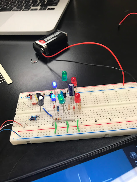
Tony then handed the circuit off to me, and I had a chance to mess with it and investigate why we were not observing a frequency response. After roughly two days of fiddling with the circuit and becoming frustrated, I decided to rebuild it all together. Again, the LEDs were not lighting up. Funny mistake, we forgot to consider the polarity of the LED lights, in which the short leg goes to ground. Upon realization of this, we corrected ourselves and had a working circuit.
 |
| I decided to space out the parts more for this section. |
Once we had a working system, I decided to try to tweak some values in hopes of gaining better results. One of our biggest issues was finding the right values for resistance and capacitance in our filters in order to yield cut off frequencies that would shut off certain lights. At this point, the light would come on in the correct order but would not shutt off beyond their intended frequency. Although I was able to change the frequency needed to turn on the blue and green LEDs, I was unable to find how to get a cutoff frequency.
Final Phase
After successfully creating a working circuit, we decided it'd be in our best interest to solder the circuit to a solder board. This would ensure a more robust system that would be able to take the "fall test" which would be expected on presentation day. This was my first time soldering, and luckily I was able to get a functioning and working circuit.
 |
Once the circuit was finally complete, we tested it out and found that it worked properly. However, it should be noted that we were never able to find a cut-off frequency or how to implement one into our circuit. The lights would simply play simultaneously, but would only come on at their specific frequencies.


No comments:
Post a Comment