Topics Discussed
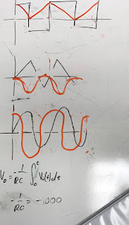
On day 15 of the ENGR 44 course, we further discussed first order circuits. We discussed unit step functions and how they can apply to RLC circuits and likewise. We also did a multitude of practice problems concerned with finding the voltages across different elements in terms of these unit step functions. (
Fig. 1) We also derivated in class the voltage of an RC circuit. (
Fig. 2) We also predicted the voltage in an RC circuit given different input voltages of various shapes.. (
Fig. 3)
Inverting Differentiator Lab
In the inverting differentiator lab, we sought to make a classic inverting differentiator using a capacitor, resistor, and op-amp. We calculated a multitude of theoretical gains when inputting different frequencies into the circuit, and we planned to use these frequencies and find an experimental gain for comparison. Sample calculations can be seen in Fig. 4.
 |
| Fig. 4 |
Once we had our experimental values accounted for, we proceeded to create the circuit. (
Fig. 5) Upon completion of the circuit, we hooked up our circuit to our analog discovery device and began taking measurement. We tried different signals at 100 Hz, 230 Hz, and 500 Hz. (
Fig. 6, Fig. 7, Fig. 8).
 |
| Fig. 5 |
 |
| Fig. 6 - 100 Hz |
 |
| Fig. 7 - 230 Hz |
 |
| Fig. 8 - 500 Hz |
Once our measurements were taken, we created a table to document our theoretical versus experimental gains. We found that our highest percent error was below 8%. (
Fig. 9)
 |
| Fig. 9 |
Summary
In today's lab, we were able to verify the theoretical gains and our perceived relationship of input to output voltage of an inverting differentiator. With a percent error of less than 8%, our predicted gains at different frequencies held true.


No comments:
Post a Comment