Wednesday, June 14, 2017

Final Project - Color Organ

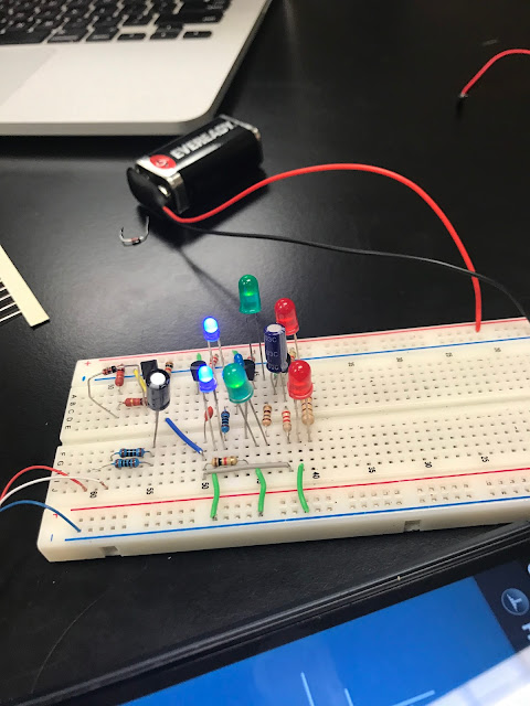
For the final project of the ENGR 44 course, Tony Li and I decided to create a color organ. A color organ is a device that uses an AC circuit to emit different color light at different frequencies. When applied with music, the color organ would correspond to the bass, mids, and highs being played.

Intended Operation
The color organ was intended to use an audio signal to light up different color LEDs, in our case red (bass), green (mids), and blue (highs). Ideally, these LEDs would only play the sounds at these frequency, and not at others. That is, as soon as a frequency surpasses the bass frequency, the red LED would turn off and the green LED would turn on.

Criteria for Success
There were two major criteria for success in our project:
1.) The color organ must emit different colors of light at different sound frequencies.
2.) Low frequencies would correspond to red LEDs, mid-level frequencies would correspond to green LEDs, and high frequencies would correspond to blue frequencies.

Pert Chart

Planning Phase
We began researching schematics and techniques for building a color organ. We came across a circuit that used transistor based filters in order to control when certain LED's would light up. We should the schematic to the professor and gained approval. 

Development Phase
Once we gained approval, we proceeded to create the actual circuit. All original parts were bought on Tayda if they could not be found in the engineering classroom. Tony was the first to get his hands on any parts, and thus he used a breadboard to get an initial feel for the circuit. We simultaneously created the EveryCircuit for the schematic above 
Add caption

List of Initial Materials
  • 3x 100 ohm resistors
  • 1x 180 ohm resistors
  • 1x 270 ohm resistors
  • 2x 1k ohm resistors
  • 4x 2.2k ohm resistors
  • 2x 10k ohm resistors
  • 1x 0.047 uF capacitor
  • 1x 0.01 uF capacitor
  • 1x 0.47 uF capacitor
  • 1x 1 uF capacitor
  • 1x 10 uF capacitor
  • 1x 1N4148 diode
  • 1x 2N2222A, 2N3904 or equivalent NPN transistor
  • 3x 2N2907A, 2N3906 or equivalent PNP transistor
  • 9x LED (3x Red, 3x Green, 3x Blue)

Initially, we had trouble getting the circuit to correspond to an alternating frequency. The lights would simply remain on.
Tony then handed the circuit off to me, and I had a chance to mess with it and investigate why we were not observing a frequency response. After roughly two days of fiddling with the circuit and becoming frustrated, I decided to rebuild it all together. Again, the LEDs were not lighting up. Funny mistake, we forgot to consider the polarity of the LED lights, in which the short leg goes to ground. Upon realization of this, we corrected ourselves and had a working circuit. 
I decided to space out the parts more for this section.
Testing Phase
Once we had a working system, I decided to try to tweak some values in hopes of gaining better results. One of our biggest issues was finding the right values for resistance and capacitance in our filters in order to yield cut off frequencies that would shut off certain lights. At this point, the light would come on in the correct order but would not shutt off beyond their intended frequency. Although I was able to change the frequency needed to turn on the blue and green LEDs, I was unable to find how to get a cutoff frequency.

Final Phase
After successfully creating a working circuit, we decided it'd be in our best interest to solder the circuit to a solder board. This would ensure a more robust system that would be able to take the "fall test" which would be expected on presentation day. This was my first time soldering, and luckily I was able to get a functioning and working circuit. 

Once the board was completed, we decided to create an enclosure that would add to the robustness of the circuit. Using acrylic sheeting and a few screws, we were able to properly cover the front and back of the circuit. It is by no means a pretty sight, but granted we weren't able to laser cut to precision the acrylic sheets.

Once the circuit was finally complete, we tested it out and found that it worked properly. However, it should be noted that we were never able to find a cut-off frequency or how to implement one into our circuit. The lights would simply play simultaneously, but would only come on at their specific frequencies. 


Day 25 - Filters

Topics Discussed
On day 25 of the ENGR 44 course, we were introduced to filters and the different types of filters would could make in a circuit. Essentially, there are four types of filters one could create: High-Pass, Low-Pass, Band-Pass, and Band-Stop. (Fig. 1)
Fig. 1
Each type of filter has its own corresponding transfer function which can describe it. We did some practice finding bandwidth and the quality factor as well from the previous lecture. (Fig. 2)
Fig. 2
Passive RL Filter Lab
In lab, we created a passive RL filter. The circuit would act as either a low-pass or high-pass filter depending on whether or not the voltage is measured across the inductor or resistor. We calculated the specific cut-off frequency for this circuit. (Fig. 3)
Fig. 3
Once we found our cut-off frequency we proceed to actually build the circuit. (Fig. 4)
Fig. 4
We then proceed to analyze the voltage across the entire circuit and the voltage across the inductor and resitor at different frequencies. We tried frequencies ranging from 1/10 the cut-off frequency to 10 times the cut-off frequency. (Fig. 5)
Fig. 5
We then calculated the gain, phase shifts, and determined if the circuit behaved as intended. (Fig. 6)

Fig. 6
Summary
On the final day of lecture for the ENGR 44 class, we were able to successfully build a circuit that filter out high frequencies and low frequencies according to whether we were measuring across the inductor or capacitor. This premise is what allowed Tony and I to create a color organ for our final project, as the circuit intended to filter out different frequencies to play specific color lights for the bass, mids, and highs. The semester has been interesting, and the class has been a challenge and kind of rewarding in a sense. God bless America.

Day 24 - Bode Plots

Topics Discussed
Today in class we discussed Bode plots. Bode plots are essentially semi-log plots that utilize the decibel scale and phase shifts. They are a plot of a transfer function and frequency. From the general form, one can pull four factors: the gain K, a pole (jω)− or zero (jω) at the origin, a simple pole 1/(1 + jω/p ) or zero (1 + jω/z ), and a quadratic pole 1/*1 + j2ζ ω/ω + (jω/ω )+ or zero *1 + j2ζ 1 ω/ω + (jω/ω )].  We also discussed resonance, a condition in which a capacitor and inductor have the same reactance. This allows the load to have maximum power at a resonance frequency denoted as ω0. There is a half power frequency next to the resonance frequency on either side, and the distance between the two is known as bandwidth. The quality factor Q is then quantified as  ω0/B. This quality factor represents the how sharp the frequency response is. There was no lab today.

Day 23 - Frequency Dependence and Transfer Functions

Topics Discussed
On day 23 of the ENGR 44 course, we discussed frequency dependence and transfer functions. The transfer function H that we defined in class can be written in four different contexts: 1) Voltage Gain: Vout/Vin 2) Current Gain Iout/Iin 3)Transfer Impedance Vout/Iin 4) Transfer Admittance Iout/Vin. We also discussed the decibel scale. We did several practice problems utilizing these new ideas. (Fig 1 and Fig. 2)
Fig. 1
Fig. 2

Signals with Multiple Frequency Components Lab
In lab today, we made a circuit in which we would analyze the frequency response. We first did some calculations to develop an understanding of how the circuit would work. We also found the transfer function of the circuit. (Fig. 3) We followed the schematic in the lab manual and applied different resistors throughout to gain different results. (Fig. 4)
Fig. 3
Fig. 4
Summary
We were able to successfully create a circuit in which we could analyze the frequency response. We found that as input frequency increased, the gain decreased and vice-versa. By analyzing this circuit, we are able to apply the concepts learned today to future discussions.

Day 22 - Apparent Power and Power Factor

Topics Discussed
On day 22 of the ENGR 44 course, we were introduced to different forms of power and how we could calculate and make sense of these types of power. These types of power come about as a result of AC circuits. Using the methods of dc circuits for power in application with ac circuits ultimately just shows us the instantaneous power. There is complex and apparent power which are integrated into AC circuits, and they have their own methods of calculation which we discussed. In order to get these different types of power, we also had to have an understanding of RMS current and voltage. We did many practice problems with these methods (Fig. 1, Fig. 2, Fig. 3)
Fig. 1
Fig. 2
Fig. 3
Apparent Power and Power Factor Lab
In lab, we planned to analyze a circuit that utilized two resistors and an inductor and find the different types of power through it. We followed the schematic in the lab and created the circuit (Fig. 4)
Fig. 4
We were able to utilize the methods discussed in class to find the apparent and complex power, as well as the power factor of the created circuit. 

Summary
Upon completion of the lab and class meeting, we were able to find apparent and complex power, as well as the total power that can be experienced across different elements in a circuit. These types of power utilize values uncommon in previous class discussions. We were also able to find the power factor of the circuit which came about as part of the phase shift found from the circuit. 

Day 21 - Oscillator

Topics Discussed
On day 21 of the ENGR 44 course, we were introduced to op-amps that were integrated into AC circuits. We used impedance instead of resistance to find the gains in each circuit, but we utilized the same equations previously discussed for op-amps. We did a few practice problems that utilized the same methods as previously, only working now in the complex domain and using impedance. (Fig. 1)
Fig. 1
We were also introduced to oscillators, which essentially create an ac waveform in its output when supplied by a dc source. 
Op-Amp Relaxation Oscillator
Today in lab, we planned to investigate an op-amp oscillator, which would utilize a dc input and output an ac waveform. In order to do this, the Barkhausen criteria have to be met. That is, the overall gain of the oscillator must be unity or greater, therefore stating that losses must be compensated for by an amplifying device. Additionally, the overall phase shift from input to output must be zero.

Once we understood the workings of the oscillator, we proceeded to make the circuit according to the lab manual specifications. (Fig. 2)
Fig. 2
We then measured the output signal to see if we had an ac waveform. (Fig. 3) This wave showed that we were able to successfully create an op-amp oscillator.
Fig. 3
Summary
Today, we were able to successfully create an oscillator using an operational amplifier. Putting in a dc circuit, we were able to generate a waveform in the output. This alternating voltage came about due to the charging and discharging of the capacitor in the circuit, which essentially allowed the voltage to fluctuate and thus create the ac signal that we were reading. 

Day 20 - Sinusoids and Phasor Cont.

Topics Discussed
On day 20 of the ENGR 44 course, we further discussed sinusoids and phasors, integrating previous circuit analysis methods into these AC circuits.Interestingly, having an understanding of how to work in the complex domain of numbers makes these methods relatively simple. We focused on using nodal analysis, but also were introduced to mesh analysis as well. (Fig. 1)
Fig. 1
We did a few problems that focused on mesh analysis (Fig. 2). We did no lab since the lab for this day was the same as the previous.
Fig. 2
Summary
Although there was no lab to get actual hands-on learning, we were able to apply some old skills to new problems and thus develop a better understanding of how to analyze AC circuits. 

Monday, June 12, 2017

Day 19 - Sinusoids and Phasors Cont.

Topics Discussed
On day 19 of the ENGR 44 course, we had further discussion of sinusoids and phasors. Additionally, we were introduced to the concept of impedance in different elements of a circuit such as capacitors, inductors, and resistors. We were also introduced to the concept of admittance which is essentially the inverse of impedance. We did several practice problems with these ideas in mind. (Fig. 1) We also discussed the concept of leading and lagging in terms of voltage and current, and how different elements within the circuit can experience this. (Fig. 2)

Fig. 1
Fig. 2
Impedance Lab
In lab, we planned to investigate the effects of a sinusoidal voltage at a set frequency on a capacitor, resistor, and inductor in three separate circuits. We wanted to use frequency at 1kHz, 5kHz, and 10kHz. We then converted these to omega and made some calculations in reference to the responses we should get. (Fig. 3)
Fig. 3
Once the calculations were complete, we then proceeded to create each circuit. (Fig. 4,5,6
Fig. 4 - Inductor
Fig. 5 - Capacitor
Fig. 6 - Resistor
We then applied the three different frequencies to each circuit and observed the effects on the voltage gain across each. (Fig. 7-15)
Fig. 7 - Inductor @ 6280 Hz

Fig. 8 - Inductor @ 31 kHz

Fig. 9 - Inductor @ 62 kHz
Fig. 10 - Capacitor @ 6283 Hz
Fig. 11 - Capacitor @ 31 kHz
Fig. 12 - Capacitor @ 62 kHz
Fig. 13 - Resistor @ 6283 Hz
Fig. 14 - Resistor @ 31 kHz
Fig. 15 - Resistor @ 62 kHz
Summary
Upon completion of the lab, we were able to successfully view the effects of applying these different frequency voltages to these separate elements in each circuit.

Day 18 - Sinusoids and Phasors

Topics Discussed
On day 18 of the ENGR 44 course, we were introduced to the topics of sinusoids and phasors. Sinusoids are signals that vary according to an alternating sine or cosine function. We did several practice problems with these concepts. (Fig. 1) We also discussed using phasors which are phase shifts within these sinusoids. We practiced several methods used to add, subtract, multiply, and divide these phasors, including how to convert them from polar to rectangular coordinates and vice-versa.
Fig. 1
Passive RL Circuit Response Lab
In lab we planned to make an RL circuit and analyze the effects on said circuit when applying a sinusoidal voltage function. Using the phase shift within our calculations, we were able to find theoretical amplitude gains that were given by a formula within the lab manual. (Fig. 2)

Fig. 2
Once we had our theoretical values, we then proceeded to create the circuit and analyzed the phase shift and gains and found that we were relatively close to our theoretical values. (Fig. 3)
Fig. 3
Summary
Upon completion of the lab, we were able to successfully analyze an RL circuit that had an alternating voltage applied to it. We were able to find the gain and phase shift across the inductor and resistor. Since AC circuits are the most common circuits we find based off of the alternating nature of circuits in our day-to-day lives, being able to properly investigate the effects on certain elements in the circuit becomes extremely useful. 

Day 17 - Second Order Circuits Cont.

Topics Discussed
On day 17 of the ENGR 44 course, we further discussed the topic of second order circuits and how to analyze different elements within the circuit. We were introduced to new techniques and again did some practice problems. (Fig. 1)
Fig. 1
RLC Circuit Response Lab
In lab, we planned to investigate how another version of an RLC circuit would respond when an alternating voltage was applied to it. We calculated values for the theoretical natural frequency and oscillation frequencies. (Fig. 2) Once these values were found, we built the circuit. (Fig. 3)

Fig. 2
Fig. 3

Summary

Despite some alteration to this circuit as opposed to previous RLC circuits, we were able to use the same methods to find several of the characteristics of the circuit, such as natural frequency, oscillation frequency, and whether the system could be considered critically, over-, or under-damped. 

Day 16 - 2nd Order Circuits

Topics Discussed
On day 16 of the ENGR 44 course, we discussed 2nd order circuits. We discussed heavily the importance of understanding the initial conditions of RLC circuits and how they can be used to determine the behavior of these circuits. We also discussed source-free circuits and the tools and equations that can be used to uncover how these circuits behaved. We did a multitude of problems focusing on whether a system was damped, over damped, or critically damped. (Fig. 1) Additionally, we did some practice with source free circuits with granted initial conditions. (Fig. 2). We further derived some expression that we would commonly use throughout these types of problem. (Fig. 3)
Fig. 1
Fig. 2
Fig. 3
Series RLC Circuit Step Response Lab
In lab today, we investigated the voltage response of an RLC circuit when inputting a square wave voltage. We intended to find the alpha, tau, natural frequency, damping ratio, and other various pieces of information relative to our circuit. We first drew up a schematic for the circuit and found the according pieces of information that would be used as our theoretical values. (Fig. 4) Once this was complete, we proceeded to create the actual circuit. (Fig. 5
Fig. 4
Fig. 5
Upon completion, we ran the circuit and proceed to analyze the voltage response. (Fig. 6) We drew up several experimental values and compared them to what was originally expected.

Fig. 6
Summary
Upon completion of the lab, we were drawn to one value in particular that stuck out, which was our measured/experimentally calculated tau. We had originally expected a much shorter period for a single oscillation but found one to be relatively 1/4 of a second. This may have been accounted for in the additional resistance of the circuit, which would have increased our alpha and thus decreased our tau.